
Views And Regions
Foldnano shows the same design through three coordinated views. They never disagree: an edit in one updates the others live.
| View | Pane | Best for |
|---|---|---|
| Strand view | Right | Routing scaffold/staples, sequence, selection, annotation |
| Plane view (lattice or freeform) | Left → Plane | Placing and moving virtual helices |
| 3D view | Left → 3D | Inspecting lab-frame geometry, plane editing, simulation, export |
The left pane switches between Plane and 3D with the Plane / 3D toggle in its toolbar. The right pane is always the strand viewer.
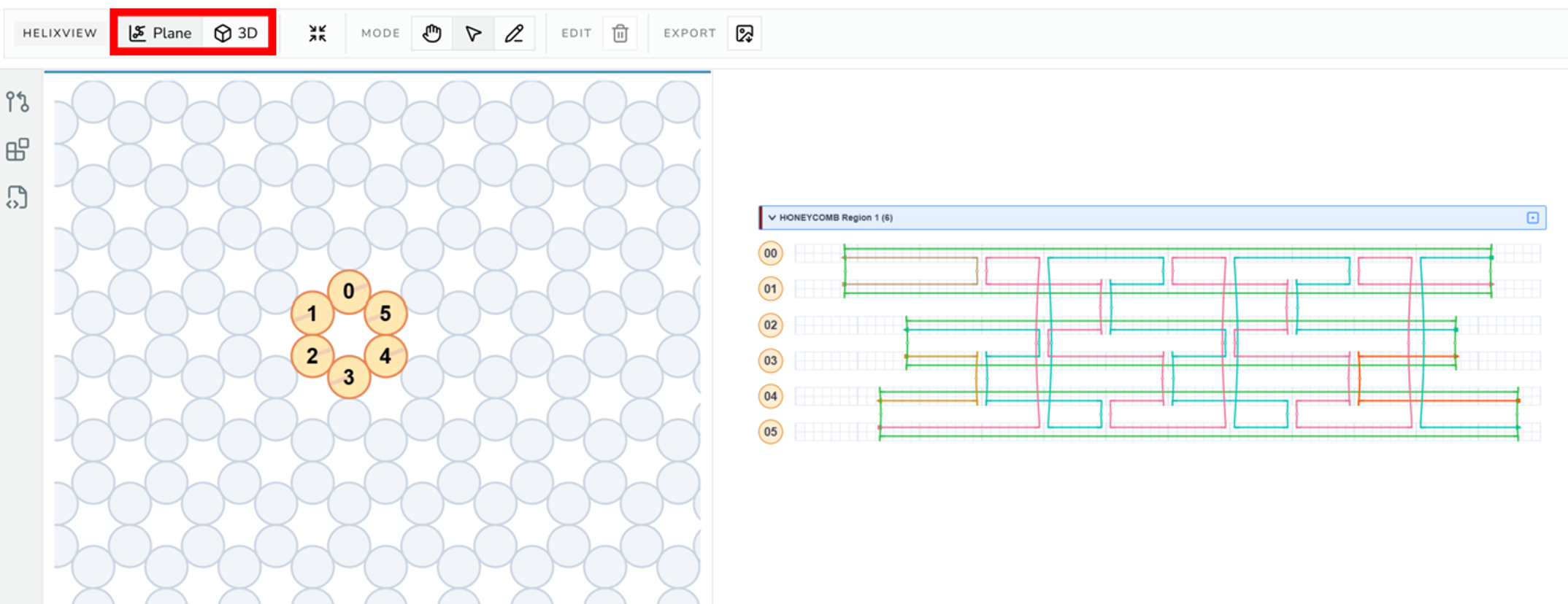
Editor with the left-pane Plane / 3D toggle highlighted, Plane active on the left and the strand viewer on the right.
Strand View
The strand view is the routing canvas. Rows are grouped by design region, and each region gets a collapsible header row. Each visible virtual helix has a draggable VH tag at its left edge.
To move around, use the arrow keys to pan (hold Shift for bigger steps), the mouse wheel to zoom, or hold Option / Alt and drag. Reset view in the strand-view toolbar returns to the default zoom. Arrow keys pan only while the strand view is the active pane (click it first).
- Click a region header (Select mode) makes that region the active region; double-click it to collapse or expand its rows.
- Drag a VH tag (Select mode) reorders that VH within its region. This changes only the display row; identity and crossovers are unaffected.
- Click a VH grid cell activates the cross-section cursor for that region.
- Drag the vertical cursor bar changes the current base (bp) index.
- Click the plane icon on a region header to jump to that region's plane in 3D: the left pane switches to 3D, planes are shown, and the camera frames the plane.
- Cross-region arrows mark strands that continue into another region.
The cross-section cursor is a shared position that drives lattice helix-circle scaffold indicators and 3D cursor markers, so you can line up the same base index across all three views.
Lattice Plane View
Used for honeycomb and square regions. Helices appear as circles on a snapped grid.
- Click empty lattice cells (Draw mode) adds VHs.
- Double-click an existing helix circle fills its default strand set if empty (does not create a circular scaffold).
- Click or marquee-select helix circles (Select mode).
- Drag selected helices moves the whole selected group on the lattice.
- Invalid moves (occupied or parity-violating destinations) leave the model unchanged.
- Delete selected helices (toolbar) or
Delete/Backspaceremoves selected helices that carry no strands. - Export as image (toolbar) downloads the plane view.
Lattice movement stays snapped to cells and preserves the region's lattice constraints (spacing and parity). For the full selection behavior, see Selection.
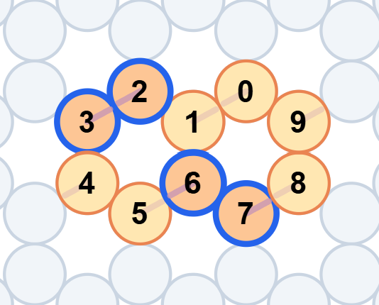
Honeycomb lattice plane with a few helix circles, one selected group highlighted in blue, and scaffold indicator lines driven by the cross-section cursor.
Freeform Plane View
Used when helix positions should not snap to a lattice. The 2D editor draws on the region plane's own (local) surface; like any region, that plane can be repositioned and reoriented in 3D with the plane gizmo.
- Double-click empty space (Draw mode) adds a perpendicular VH.
- Drag in empty space (Draw mode) creates an in-plane VH.
- Click a perpendicular VH (Draw mode) fills it with a strand.
- Click a free 3′ end, then a free 5′ end (Draw mode) connects them.
- Drag selected VHs moves them.
- Opacity shows depth. The view looks along +W, so VHs at more negative W are nearer and more solid, and VHs at more positive W are fainter. Where VHs overlap, the nearer one is on top and takes the click. Selected and hovered VHs stay solid.
- Drag a rotate handle rotates one in-plane VH.
- Drag a free endpoint (Select mode) resizes that segment.
- Distribute in a circle (plane view toolbar) spaces three or more selected perpendicular VHs evenly on a circle around their centre, keeping their order. Its sibling, Distribute in a circle, facing the centre, also rolls each VH so roll 0 points at the centre.
Freeform edits update each helix's explicit local frame, which is preserved in .fn.json but not in cadnano JSON.
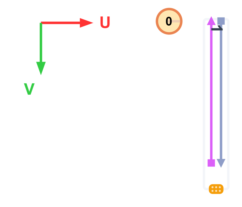
Freeform plane showing a perpendicular VH (circle) and an in-plane VH (line) with its rotate handle visible.
Multiple Regions
A design can contain more than one region, for example a lattice bundle connected to a freeform extension. Each region has its own plane, its own placement rules, and its own grouped block of rows in the strand viewer.
Note
DNA can continue from one region into another whenever the ends are compatible. Region boundaries affect placement rules and UI grouping, not whether a strand can physically cross between regions. Keep an eye on cross-region crossovers when you later run auto-staple, simulation, or export.
3D View
The 3D view shows the current design in lab coordinates. It can display:
- helix cylinders and labels
- strand and crossover geometry
- cross-section cursor markers
- a coordinate axis
- persisted plane overlays
- the rigid-body simulation preview
The 3D toolbar controls what's shown and what runs:
- View toggles: helix grid (
g), NT model (e), cross-section cursor (c), coordinate axis, and base planes (f). The keys work while the 3D view is the active viewer. - Selection: show only the strands selected in the strand viewer, and lock that filter so further selection changes don't affect the 3D view.
- RBS (rigid-body simulation): Relax, relaxed layout, crossover stress, clear relaxed layout, and Params.
- Export: image (PNG), GLB, oxDNA, and mrDNA.
- Reset camera and performance stats.
- 3D Overlay, which switches the tool panel to 3D Overlays for loading mrDNA or PDB structures.
- Mesh, shown for a wireframe region, which switches the tool panel to Reference Mesh.
Every button is listed in the Interface Reference.
Next to the 3D view, the 3D View Inspector panel offers region visibility, plane visibility with Add Plane, the selected plane's details, and simulation diagnostics.
See Simulation And Export for the simulation and export workflows.
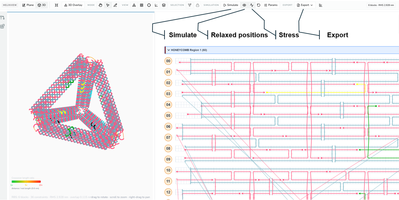
3D view of a routed design with the 3D toolbar visible, showing the RBS relax, relaxed-positions, stress, and export controls.
Hiding Regions in 3D
The Regions list at the top of the 3D View Inspector has an eye button for each region. Hiding a region removes its helices, strands, and reference mesh from the 3D view, along with any crossover that connects to it. A GLB export or screenshot leaves it out too.
Hiding is only a view setting. It isn't saved with the design, can't be undone with Ctrl/Cmd + Z, and doesn't affect the strand view, relaxation, or oxDNA and mrDNA exports. Its plane still follows the plane visibility toggle, so you can keep repositioning it.
Plane Gizmo
Plane editing happens from the 3D view:
- Switch the left pane to 3D.
- Enable plane visibility.
- Click a visible plane to select it.
- Choose translate or rotate mode.
- Drag the gizmo.
The model updates live during the drag and records a single undoable history entry when the drag ends, so a whole reposition is one Ctrl/Cmd + Z.
The 3D View Inspector panel shows the selected plane's name, origin, and normal, and has its own rotate / move toggle. Add Plane creates a new plane based on the selected one. Remove Plane appears for a plane that no region uses (the last plane can't be removed).
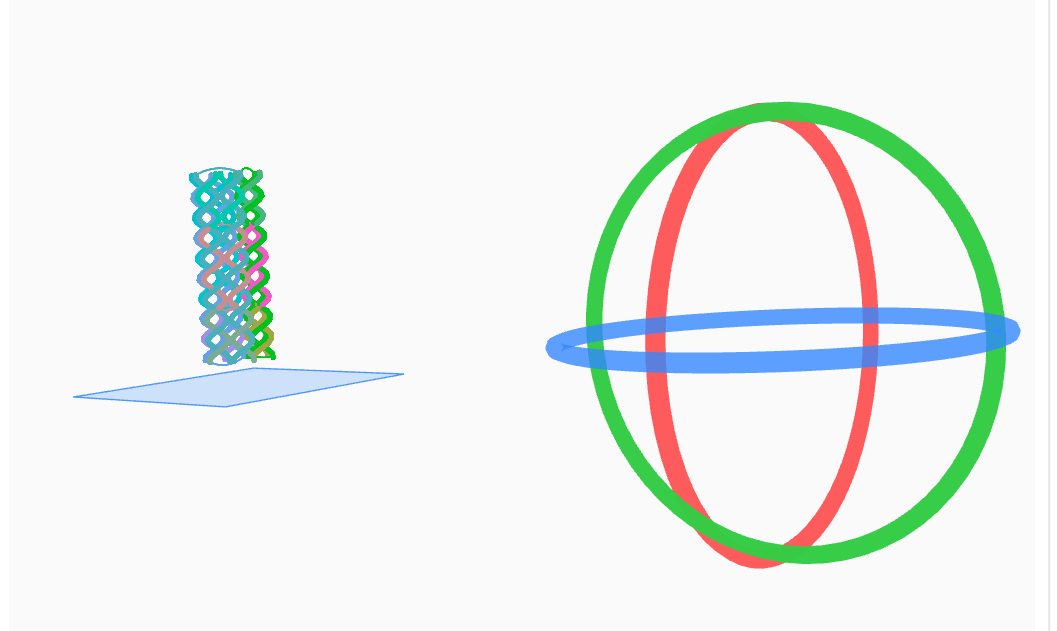
Plane gizmo active in the 3D view, showing the rotate handles (red, green, blue rings) on a selected plane.